RADIO
Jack Schmidling Productions, Inc.
Marengo Illinois
MOST RECENT PHOTOS PHOTO INDEX HOME PAGE
New SLIDE SHOW New
HAM RADIO
This seems like a good time to introduce one of my other life-long hobbies. In 1955, I accomplished one of my first major life goals. I passed all the tests for an Amateur Radio License. It was just the entry level "Novice Class" license but it allowed me to "talk" via Morse Code to people all over the world with simple equipment that I built myself.
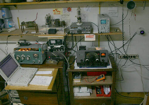
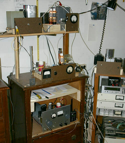
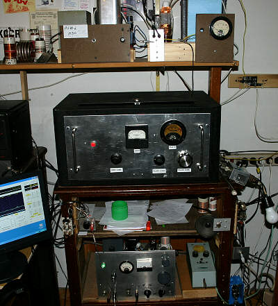
My career, family and other hobbies pressed hard on my free time so "ham radio" has faded in and out of my life over the years. I have recently been re-bitten by the bug and this clutter of stuff represents my current operating "station". It is neither the latest technology nor does it remotely resemble what my high school budget would allow. I should also add that it does not remotely resemble what a typical ham station looks like, but it's me.
One of the most interesting objects in this picture is the post card near the center with the red letters. This is what hams call a QSL card. QSL is Morse Code shorthand for "roger" " understood" or "confirmation". The big red letters are my FCC assigned call sign and the rest contains information to confirm the time, place and method of a radio conversation or QSO. After filling in the info, the card is mailed to the other station and hopefully he/she will have the courtesy to respond in kind.
What makes this particular card so interesting is that it is the last of my very first set of cards that I purchased in 1955 just after getting my license. You will note the"N" in the KN9ACT which indicates that this is a "Novice" license which expires after one year. This allows the beginner a year to increase proficiency in Morse Code and technical background so that he/she can be qualified to upgrade to a higher and permanent class of license. I currently hold the Extra Class license which is the highest grade but have the same call sign, (minus the N) as I did in 1955.
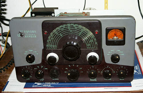
The Ranger
My first project as a born-again ham was to acquire an amplitude modulated transmitter with real tubes in it. I was told that the Viking Ranger was one of the classics of choice so I acquired this one.
Unfortunately, it had been butchered almost beyond recognition but with lots of help from internet hams and about 3 weeks of obsessive futzing, it is now on the air and working well. Part of the ambience of all this old stuff is the tubes so the cover is hidden away somewhere and will probably never see the light of day again.
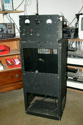
813's
My next and current project is to turn this carcass into the mantra of my early ham days. All the real men had "an 813 modulated by a pair of 811's which were the tubes of choice in those days. All I could afford was an 807 modulated by a telegraph key, i.e. no phone/voice at all.
I acquired this stuff for a very modest price and have some of the basics needed for my "mantra rig".
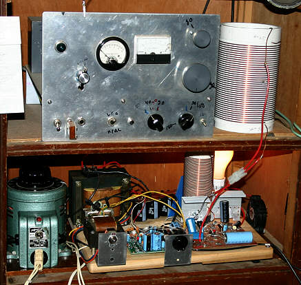
It was or was on it's way to being a linear amplifier with a pair of 813's but this is a mere shadow of the real thing. So I have a nice cabinet, most of a power supply and some tubes and parts.
The blank panel in the middle is where the modulator will go.
You can see what there is of the rf deck on the top shelf of the first photo.
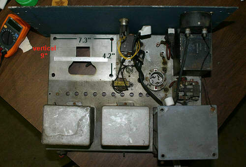
POWER SUPPLY
This is the power supply as received. As can be seen it is lacking in few fundamentals like a power transformer, rectifier tubes and a socket.
I think I have a transformer lined up for it and all the rest is now in order.
Meanwhile, the Ranger and the Heathkit SB200 (green box on left in top photo) are serving me well enough.
73 for now
JACK K9ACT
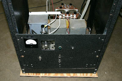
POWER SUPPLY
This is the power supply ready to go with the new transformer mounted on an extension of the dolly in the rear and everything else in apple pie order.
Note the window in the front panel to allow viewing of the beautiful glow of the mercury vapor rectifiers.
This supply will produce either 1600 or 2000 volts DC at 500 ma, depending how it is wired up.
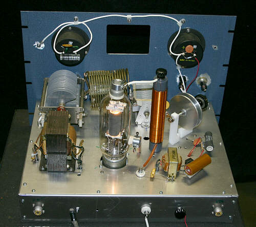
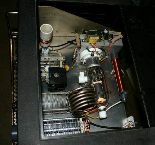
RF DECK
If you go back up to the first picture, you will notice my "nicknack" tube sitting on top of the Kenwood 430. I have been hauling this around with me since my Coast Guard days and basically using it as a bookend.
Several weeks ago I found out what it is in an old manual and discovered that it was actually a better tube than the 813 for my purposes. So I abandoned my mantra and switched to an 8000 modulated by 811's.
This picture shows it's current status in progress as of
Feb 09, 2007.
Notice again, the window so I can watch the tube glow.
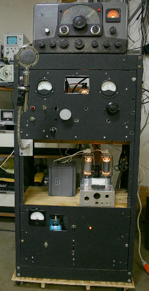
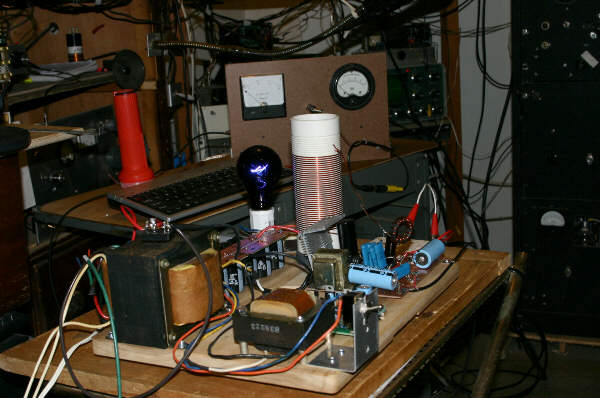
The Whole Shebang
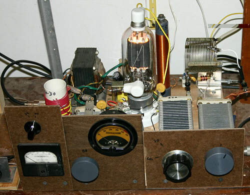
This is the status as of Feb 23 after the first sea trials and a few good news reports of how it sounds.
If you go back up again to the first picture, you will notice a small chassis with a pair of 813's next to the Kenwood. This was destined by the original builder to be a linear amplifier. To me it was of little value until I learned that 813's as triodes make wonderful modulators and could operate at the same voltage as the 8000.
This chassis now appears in the modulator deck next to the mod transformer. It contains the pair of 813's, a filament transformer, a meter and some wires. The 813's are configured as triodes with the screens and grids tied together and seems to work quite well.
I am currently running it at 1500 volts to establish some confidence in the rig before re-wiring the HV transformer for 2000 volts.
For the record, I must credit Dan Hopper K9WEK with unlimited (almost) patience helping me with the design of this project. I only knew enough to rough out the basic schematic and Dan filled in the blanks and helped with many of the esoteric details.
My credit extends to building it and having the fortitude to fire it up.
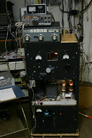
After getting it working and on the air for a few weeks, I decided that driving with the Ranger was a good way to get it going but lacked the satisfaction of being able to say I made the whole shebang.
So, the next step seen here is the speech amplifier which I made from solid state kits to take the place of the audio portion of the Ranger. It contains a mic preamp and a 20W power amplifier. This is all behind the little panel in front of the 813 modulator tubes along with the 12 volt supply.
I have also changed microphones and added a graphic equalizer which can be seen on the left.
For now, I am exciting the RF deck with the Kenwood and working on a homebrew exciter using a 6AG7 VFO, 6CL6 buffer and 807.
Under the Kenwood can be seen the antenna tuner which I have recently added to match a new ladder line antenna. The o'scope sits next to the tuner when not being used elsewhere.
As can be seen from the blue glow of the 866's and meters, it is powered up to about 250 W carrier.
This is a bit out of the time line but is probably the end of this project. In late October 2007, I decided to take it one step further and add another 8000 in parallel to get it up to full legal limit without pushing anything too hard.
I upgraded the plate tank cap to handle more power, had to double up on the neutralizing cap and change the bias resistors but other than rearranging some parts, it was pretty straight forward.
It now loafs along with a 400 watt carrier well below the CCS service ratings.
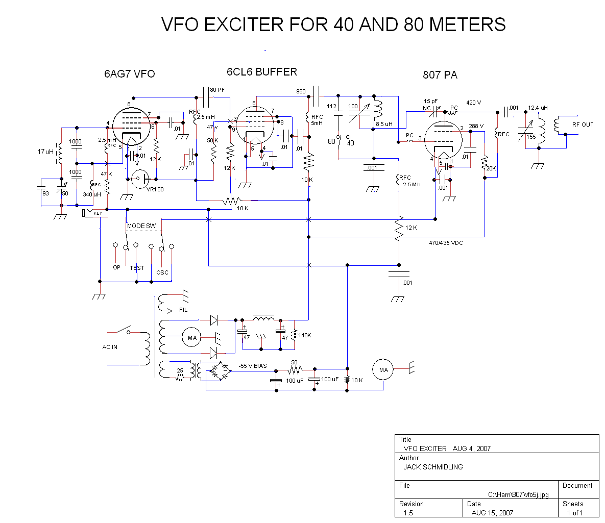
THE RF EXCITER
This is what the first breadboard of the exciter looked like. The mess on the left is the VFO.
The 807 self destructed so I substituted a 6146 until I could get a replacement. Folks tell me the 807 is big trouble compared to the 6146 but I made something similar when I was a kid and just have to do it again. I was a Novice then so the VFO is something I never ventured into before.
The other problem is that I could not afford any test equipment then so ignorance was bliss.
This is more or less the final physical arragement but as of May 26, it looks a lot better than it works.
As of early August, it works like a charm. The major cause of delay was deciding as an afterthought, to make a CW transmitter out of it. This presented all sorts of new problems that I never contemplated or needed for an AM exciter. Decent keying characteristics and VFO stability are of paramont interest and not trivial problems.
It works like a charm now and I use it both to excite the AM rig and to re-live my Novice days on 40 meter CW.
This low resolution shematic shows the basic plan. If you would like a high resolution view, click here
HIRES Schematic
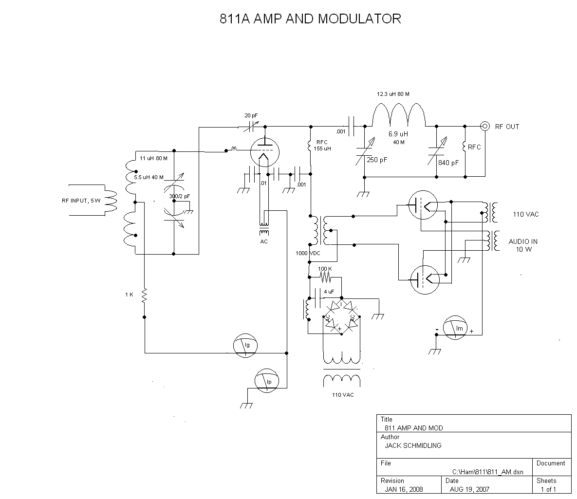
811A Class C Amplifier
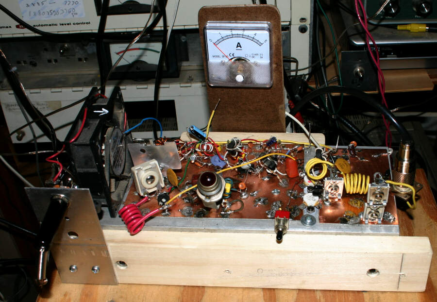
There seems to be no end in sight for this building frenzy. No sooner did I almost finish the exciter than I discovered that 10W on CW is not my cup of tea. I happen to have a pair of 811's not used on the AM rig so I started turning them and a pile of other people's junk into an amplifier.
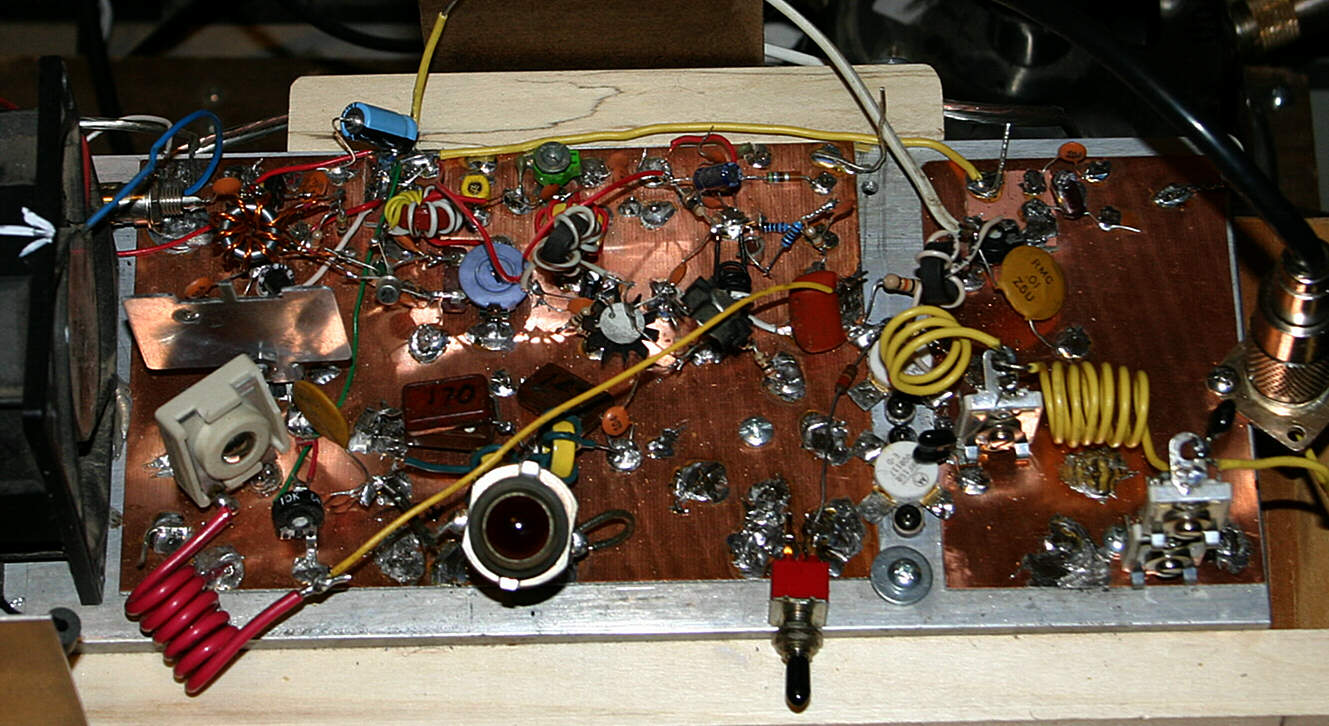
This breadboard is what it looks like as of Aug 29, 2007 and it actually works. Puts out about 100 W on 40 meters. Worked a ham in Idaho tonight.
I am still trying to decide if I want to go whole hog and use both 811's or just save the extra for a spare.
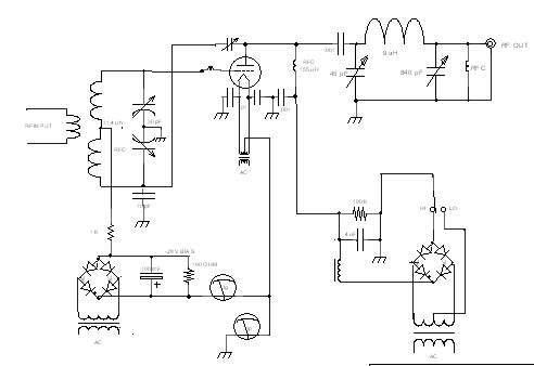
This low resolution shematic shows the basic plan. If you would like a high resolution view, click here
HIRES Schematic
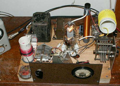
One thing leads to another around here and the CW rig has now become a full fledged plate modulated AM transmitter.
This is how it looks as of Oct 30, 2007.
Starting at top left is the modulator power supply and to it's right, the 811 Class B modulator.
Below that is the 811 RF deck and to the right, it's power supply.
I first ran it with only one power supply (1kv@250ma) and it worked fine but wanted to see if separate supplies would make any difference and it does not seem to be worth the trouble.
Under the RF deck is the VFO/Exciter and to it's right, the graphic EQ and CBS audio chain.
As can be seen, all the "temporary" wood and Masonite breadboarding is still there and works fine so it will probably remain temporary.
So now I am an empty nester is search of a new hobby.
Well, that didn't last long and idle hands being the Devil's workshop,
I reworked the design to use an 810 instead of an 811A.
I also beefed up the RF Deck power supply with a 1700V transformer and it now
runs about 225W carrier with full modulation.
The wood and Masonite version may have looked very nice but I was suspecting
that it may have been part of the problem I was having with my SoftRock crashing.
While I was gassing with someone at the Hamboree, my wife bid $1
for a mystery box that no one else wanted. I didn't either but you know wives.
By the time I got half way home, I knew exactly what I was going to do with it.
After about a week of quality time working out the layout and figuring out how to get
a 10" tube in a 9" cabinet, it is no longer a source of RFI in the shack.
Of course it did not solve the problem with the SoftRock but it was a fun project.
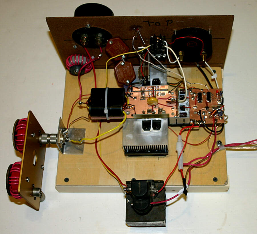
This is the inside view with 20 meter coils installed.
The small transformer on top of the socket mount is for the bias supply.
The fil trans is on the backside of the mount.
The little black box was just a handy mount for the neut cap.
Class D Transmitter
My next project was to find out what Class D, E and Pulse Width Modulation were all about.
In the background is the 200W RF deck based on a design by W1VD.
http://www.w1vd.com/375wattclassD.html
In the foreground is the PWM modulator based on the design of WA1QIX
This is the inside view of the RF deck. Signal conditioning and FET drivers on the right, FET power amps in the center on fan cooled heatsinks and broadband output transformer on the left.
You will note that there are no tuning capacatiors or inductors in the output which is one of the advantages of Class D over Class E. The downside is that an antenna tuner is requred to match to the antenna.
On the far left is the 80 meter bandpass filter which can be replaced by a 160 meter one.
This is the PWM modulator on the lower shelf. The rig on the upper shelf is an unrelated driver for my other transmitters. The coil on the upper shelf is one of two coils in the output bandpass filter of the modulator.
The light bulb serves the purpose of constant load and bleeder resistor for the capacitor bank.
This will modulate the 200W RF well over 150% and by adding one more fet, wiill modulate a legal limit RF deck.
By using the Variac and carrier level control, I can also use it to modulate my 25W ten meter transmitter which is the topic of my next project.
10 Meter Class C AM Transmitter
Unable to get any of my other transmitters to work on 10 meters, I undertook to build one from scratch for ten.
What we have here from left to right is an RF deck that conditions the 14.5 MHZ VFO sig to drive a freq doubler (NB6M). This drives two RF amp stages which drive the M11:04 MRF150 150W PA stage.
Using the PWM modulator, the carrier is set for 25W and with 150% modulation, the PEP is about 150W.
The 10 meter band is just starting to open up and my trophy to date is G3UU in England this afternoon, 11/12/11 which prompted updating this page.
This low resolution view shows the basic plan. If you would like a high resolution view, click here
HIRES View
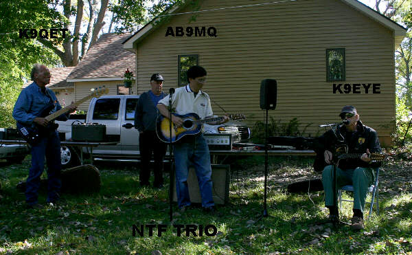
The Freefest Trio
This was the entertainment for one of our anual Oktoberfests.
OKTOBERFEST
Not our usual German band but the price was right.
The Ranger
Unfortunately, it had been butchered almost beyond recognition but with lots of help from internet hams and about 3 weeks of obsessive futzing, it is now on the air and working well. Part of the ambience of all this old stuff is the tubes so the cover is hidden away somewhere and will probably never see the light of day again.
813's
My next and current project is to turn this carcass into the mantra of my early ham days. All the real men had "an 813 modulated by a pair of 811's which were the tubes of choice in those days. All I could afford was an 807 modulated by a telegraph key, i.e. no phone/voice at all.
I acquired this stuff for a very modest price and have some of the basics needed for my "mantra rig".
It was or was on it's way to being a linear amplifier with a pair of 813's but this is a mere shadow of the real thing. So I have a nice cabinet, most of a power supply and some tubes and parts.
The blank panel in the middle is where the modulator will go.
You can see what there is of the rf deck on the top shelf of the first photo.
POWER SUPPLY
This is the power supply as received. As can be seen it is lacking in few fundamentals like a power transformer, rectifier tubes and a socket.
I think I have a transformer lined up for it and all the rest is now in order.
Meanwhile, the Ranger and the Heathkit SB200 (green box on left in top photo) are serving me well enough.
73 for now
JACK K9ACT
POWER SUPPLY
This is the power supply ready to go with the new transformer mounted on an extension of the dolly in the rear and everything else in apple pie order.
Note the window in the front panel to allow viewing of the beautiful glow of the mercury vapor rectifiers.
This supply will produce either 1600 or 2000 volts DC at 500 ma, depending how it is wired up.
RF DECK
If you go back up to the first picture, you will notice my "nicknack" tube sitting on top of the Kenwood 430. I have been hauling this around with me since my Coast Guard days and basically using it as a bookend.
Several weeks ago I found out what it is in an old manual and discovered that it was actually a better tube than the 813 for my purposes. So I abandoned my mantra and switched to an 8000 modulated by 811's.
This picture shows it's current status in progress as of
Feb 09, 2007.
Notice again, the window so I can watch the tube glow.
The Whole Shebang
This is the status as of Feb 23 after the first sea trials and a few good news reports of how it sounds.
If you go back up again to the first picture, you will notice a small chassis with a pair of 813's next to the Kenwood. This was destined by the original builder to be a linear amplifier. To me it was of little value until I learned that 813's as triodes make wonderful modulators and could operate at the same voltage as the 8000.
This chassis now appears in the modulator deck next to the mod transformer. It contains the pair of 813's, a filament transformer, a meter and some wires. The 813's are configured as triodes with the screens and grids tied together and seems to work quite well.
I am currently running it at 1500 volts to establish some confidence in the rig before re-wiring the HV transformer for 2000 volts.
For the record, I must credit Dan Hopper K9WEK with unlimited (almost) patience helping me with the design of this project. I only knew enough to rough out the basic schematic and Dan filled in the blanks and helped with many of the esoteric details.
My credit extends to building it and having the fortitude to fire it up.
After getting it working and on the air for a few weeks, I decided that driving with the Ranger was a good way to get it going but lacked the satisfaction of being able to say I made the whole shebang.
So, the next step seen here is the speech amplifier which I made from solid state kits to take the place of the audio portion of the Ranger. It contains a mic preamp and a 20W power amplifier. This is all behind the little panel in front of the 813 modulator tubes along with the 12 volt supply.
I have also changed microphones and added a graphic equalizer which can be seen on the left.
For now, I am exciting the RF deck with the Kenwood and working on a homebrew exciter using a 6AG7 VFO, 6CL6 buffer and 807.
Under the Kenwood can be seen the antenna tuner which I have recently added to match a new ladder line antenna. The o'scope sits next to the tuner when not being used elsewhere.
As can be seen from the blue glow of the 866's and meters, it is powered up to about 250 W carrier.
This is a bit out of the time line but is probably the end of this project. In late October 2007, I decided to take it one step further and add another 8000 in parallel to get it up to full legal limit without pushing anything too hard.
I upgraded the plate tank cap to handle more power, had to double up on the neutralizing cap and change the bias resistors but other than rearranging some parts, it was pretty straight forward.
It now loafs along with a 400 watt carrier well below the CCS service ratings.
THE RF EXCITER
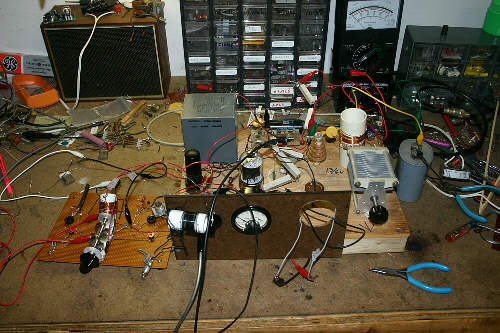
This is what the first breadboard of the exciter looked like. The mess on the left is the VFO.
The 807 self destructed so I substituted a 6146 until I could get a replacement. Folks tell me the 807 is big trouble compared to the 6146 but I made something similar when I was a kid and just have to do it again. I was a Novice then so the VFO is something I never ventured into before.
The other problem is that I could not afford any test equipment then so ignorance was bliss.
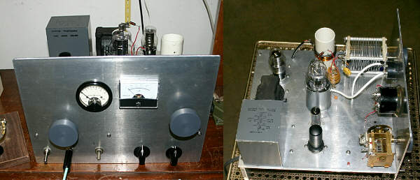
This is more or less the final physical arragement but as of May 26, it looks a lot better than it works.
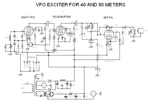
As of early August, it works like a charm. The major cause of delay was deciding as an afterthought, to make a CW transmitter out of it. This presented all sorts of new problems that I never contemplated or needed for an AM exciter. Decent keying characteristics and VFO stability are of paramont interest and not trivial problems.
It works like a charm now and I use it both to excite the AM rig and to re-live my Novice days on 40 meter CW.
This low resolution shematic shows the basic plan. If you would like a high resolution view, click here
HIRES Schematic
811A Class C Amplifier
There seems to be no end in sight for this building frenzy. No sooner did I almost finish the exciter than I discovered that 10W on CW is not my cup of tea. I happen to have a pair of 811's not used on the AM rig so I started turning them and a pile of other people's junk into an amplifier.
This breadboard is what it looks like as of Aug 29, 2007 and it actually works. Puts out about 100 W on 40 meters. Worked a ham in Idaho tonight.
I am still trying to decide if I want to go whole hog and use both 811's or just save the extra for a spare.
This low resolution shematic shows the basic plan. If you would like a high resolution view, click here
HIRES Schematic
One thing leads to another around here and the CW rig has now become a full fledged plate modulated AM transmitter.
This is how it looks as of Oct 30, 2007.
Starting at top left is the modulator power supply and to it's right, the 811 Class B modulator.
Below that is the 811 RF deck and to the right, it's power supply.
I first ran it with only one power supply (1kv@250ma) and it worked fine but wanted to see if separate supplies would make any difference and it does not seem to be worth the trouble.
Under the RF deck is the VFO/Exciter and to it's right, the graphic EQ and CBS audio chain.
As can be seen, all the "temporary" wood and Masonite breadboarding is still there and works fine so it will probably remain temporary.
So now I am an empty nester is search of a new hobby.
Well, that didn't last long and idle hands being the Devil's workshop,
I reworked the design to use an 810 instead of an 811A.
I also beefed up the RF Deck power supply with a 1700V transformer and it now
runs about 225W carrier with full modulation.
The wood and Masonite version may have looked very nice but I was suspecting
that it may have been part of the problem I was having with my SoftRock crashing.
While I was gassing with someone at the Hamboree, my wife bid $1
for a mystery box that no one else wanted. I didn't either but you know wives.
By the time I got half way home, I knew exactly what I was going to do with it.
After about a week of quality time working out the layout and figuring out how to get
a 10" tube in a 9" cabinet, it is no longer a source of RFI in the shack.
Of course it did not solve the problem with the SoftRock but it was a fun project.
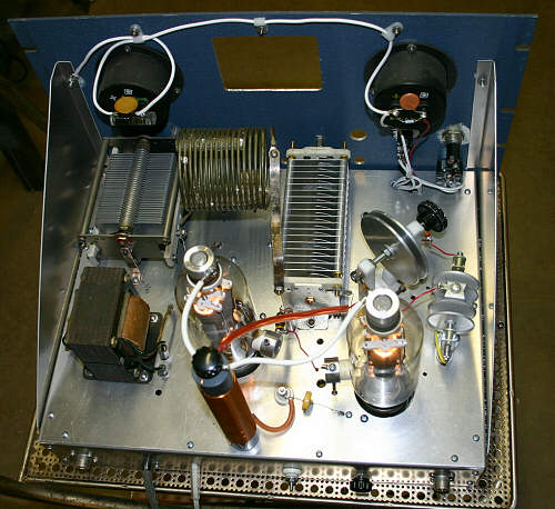
This is the inside view with 20 meter coils installed.
The small transformer on top of the socket mount is for the bias supply.
The fil trans is on the backside of the mount.
The little black box was just a handy mount for the neut cap.
Class D Transmitter
My next project was to find out what Class D, E and Pulse Width Modulation were all about.
In the background is the 200W RF deck based on a design by W1VD.
http://www.w1vd.com/375wattclassD.html
In the foreground is the PWM modulator based on the design of WA1QIX
This is the inside view of the RF deck. Signal conditioning and FET drivers on the right, FET power amps in the center on fan cooled heatsinks and broadband output transformer on the left.
You will note that there are no tuning capacatiors or inductors in the output which is one of the advantages of Class D over Class E. The downside is that an antenna tuner is requred to match to the antenna.
On the far left is the 80 meter bandpass filter which can be replaced by a 160 meter one.
This is the PWM modulator on the lower shelf. The rig on the upper shelf is an unrelated driver for my other transmitters. The coil on the upper shelf is one of two coils in the output bandpass filter of the modulator.
The light bulb serves the purpose of constant load and bleeder resistor for the capacitor bank.
This will modulate the 200W RF well over 150% and by adding one more fet, wiill modulate a legal limit RF deck.
By using the Variac and carrier level control, I can also use it to modulate my 25W ten meter transmitter which is the topic of my next project.
10 Meter Class C AM Transmitter
Unable to get any of my other transmitters to work on 10 meters, I undertook to build one from scratch for ten.
What we have here from left to right is an RF deck that conditions the 14.5 MHZ VFO sig to drive a freq doubler (NB6M). This drives two RF amp stages which drive the M11:04 MRF150 150W PA stage.
Using the PWM modulator, the carrier is set for 25W and with 150% modulation, the PEP is about 150W.
The 10 meter band is just starting to open up and my trophy to date is G3UU in England this afternoon, 11/12/11 which prompted updating this page.
This low resolution view shows the basic plan. If you would like a high resolution view, click here
HIRES View
